Armadillo-640で、下記LoRaデバイスを動かしてみました。
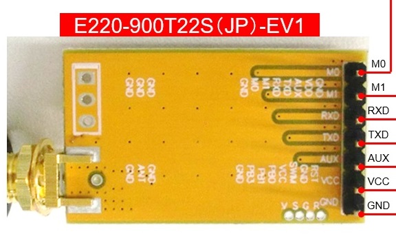
LoRaモジュール評価ボード:E220-900T22S(JP)-EV1
(以下では、「LoRaデバイス」と略称します)
LoRa用アンテナ(TX915-JKS-20)
以下の手順で動かすにあたり、
上記製品サイトの下記資料(データシート等)
を参考にさせていただきました。
ここでは、
送信側:LoRaデバイス+Armadillo-640(送信用プログラム実行)
受信側:LoRaデバイス+Armadillo-640(受信用プログラム実行)
を用意して、送信側から受信側へLoRa通信した手順を説明しています。
Armadillo-640は、二種類のOS(ABOS/Debian)に対応しています。
ここでは、Debian版を説明します。
ABOS版は、別途公開する予定です。
手順1. Armadillo-640の準備
LoRaデバイスとの接続には、UART×1(TXD/RXD)、GPIO×3(M0/M1/AUX)、電源5V(VCC)、GNDが必要です。
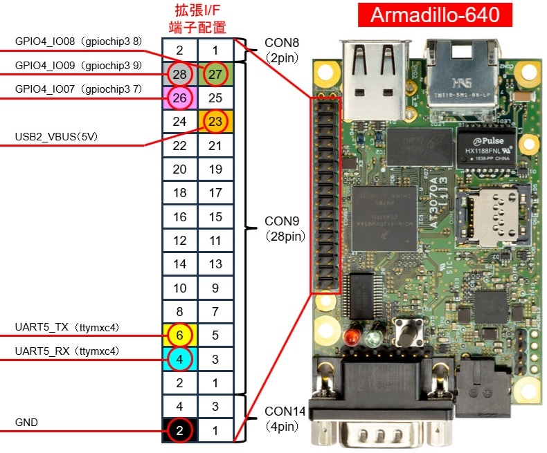
Armadillo-640の拡張I/Fの下記の端子を使います。
ここでは、Debianを使用するため、
Armadillo-640:インストール方法(手順まとめ版)を参考に
Armadillo-640 インストールディスクイメージでDebianをインストールしておきます。
実のところ、上記の方法で標準のインストールディスクイメージでインストールすると、
上記の端子設定が有効になっています。
他にカーネル、端子設定をする場合は、カーネルをビルドし直す必要がありますが、
ここでは、このまま変更せずに手順2に進みます。
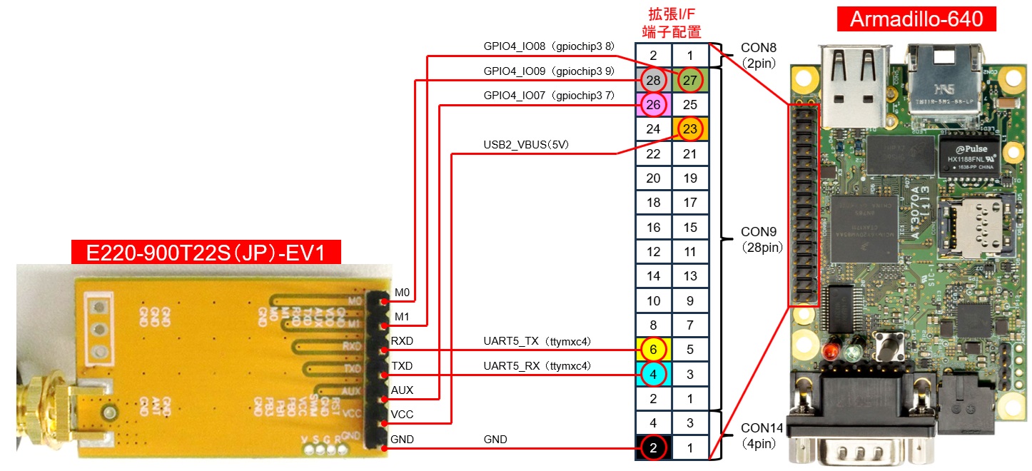
手順2. Armadillo-640とLoRaデバイスの接続
Armadillo-640の拡張I/FとLoRaデバイスの各端子を下図のように接続します。
上記端子とアンテナを接続した状態の写真です。
(双方のピンヘッダをヘッダ用接続ケーブルで接続しました)
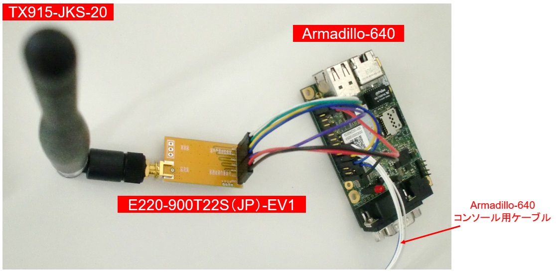
ここでは、送信/受信用に上図の状態のArmadillo-640+LoRaデバイスを2個用意しました。
手順3. プログラムの作成(はじめに)
ここでの確認では、簡易的なGPIO制御とシリアル通信のプログラムで動かしてみます。
以下のプログラムでは、エラー処理、フェイルセーフは考慮していません。
また、上図でAUXは接続していますが、以下のプログラムでは使用していません。
補足)
LoRaデバイスの製品サイトには、サンプルプログラムも用意されています。
手順4. 必要なパッケージをインストール
ここでは、pythonを使ったプログラムを作成します。
Armadillo-640をインターネットに接続可能なネットワークに接続して、
下記コマンドを実行して、必要なパッケージをインストールします。
root@armadillo:~# apt update
root@armadillo:~# apt install python3
root@armadillo:~# apt install python3-pip
root@armadillo:~# apt install python3-libgpiod
root@armadillo:~# python3 -m pip install pyserial
root@armadillo:~# python3 -m pip install timeout-decorator
手順5. ここで作成するプログラムの概要
下記のpythonプログラムを同一ディレクトリに作成します。
set_gpio.py:LoRaデバイスのM0/M1/AUX用のGPIOを設定
get_conf_all.py:LoRaデバイスのコンフィグの読み込み
set_conf_all.py:LoRaデバイスのコンフィグの設定
send_sample.py:送信
recv_sample.py:受信
手順6. プログラムの作成
以下のプログラム作成にあたっては、
LoRaデバイスの製品サイトの
「製品データシート Firmware Ver.1.0/1.2 rRev2.1.2」を参考にしてます。
set_gpio.py
import gpiod

# Set Armadillo-640 GPIO
# AUX: gpiochip3 7(CON9_26) for INPUT
# M0: gpiochip3 8(CON9_27) for OUTPUT
# M1: gpiochip3 9(CON9_28) for OUTPUT
chip = gpiod.Chip('gpiochip3', gpiod.Chip.OPEN_BY_NAME)

e220_aux = chip.get_line(7)
e220_m0 = chip.get_line(8)
e220_m1 = chip.get_line(9)

e220_aux.request(consumer='foo', type=gpiod.LINE_REQ_DIR_IN)
e220_m0.request(consumer='foo', type=gpiod.LINE_REQ_DIR_OUT)
e220_m1.request(consumer='foo', type=gpiod.LINE_REQ_DIR_OUT)

# For setting E220 Mode
# (M0, M1) = (0, 0): Normal Communication
# (M0, M1) = (1, 1): Config
def set_e220_mode(m0_val, m1_val):
  e220_m0.set_value(m0_val)
  e220_m1.set_value(m1_val)

# Set E220 Config Mode:(M0, M1) = (1, 1)
set_e220_mode(1, 1)
説明)LoRaデバイスのM0/M1/AUX用のGPIOを設定します。
プログラム内の「gpiochip3」「7/8/9」は、LoRaデバイスと接続している
Armadillo-640の「gpiochip3 7/8/9」に相当します。
本プログラム内の「set_e220_mode」は、以下のプログラムでもimportして使用します。
get_conf_all.py
import serial
import time
import timeout_decorator

# For using set_e220_mode in set_gpio.py
import set_gpio

# Set E220 Config Mode:(M0, M1) = (1, 1)
set_gpio.set_e220_mode(1, 1)

# Set serial port
ser = serial.Serial('/dev/ttymxc4', 9600)

# Read command E220 register(00h-08h: 9Byte): begin
read_cmd_conf0_8 = bytearray([0xc1,0x00,0x09])

def send_cmd(cmd):
  ser.write(cmd)

@timeout_decorator.timeout(1)
def recv_res():
 # get response: [command] [starting address] [length]
  res = ser.read(3)
  print('Response command:', res.hex())
  # get register data by [length]
  num = int(res.hex()[5:])
  res = ser.read(num)
  print('Register value[00h-08h]:', res.hex())

ser.reset_input_buffer()
ser.reset_output_buffer()

send_cmd(read_cmd_conf0_8)
time.sleep(1)
recv_res()
# Read command E220 register(00h-08h: 9Byte): end
説明)LoRaデバイスをコンフィグモード:(M0, M1) = (1, 1)にします。
コンフィグ(レジスタ:00h-08h)を読み込みます。
以降のプログラム中の「ttymxc4」は、LoRaデバイスと接続している
Armadillo-640のUART5(ttymxc4)を指しています。
UARTのボーレート(9600)は、LoRaデバイスのデフォルトに合わせています。
set_conf_all.py
import sys
import serial
import time
import timeout_decorator

# For using set_e220_mode in set_gpio.py
import set_gpio

# Set E220 Config Mode:(M0, M1) = (1, 1)
set_gpio.set_e220_mode(1, 1)

# Set serial port
ser = serial.Serial('/dev/ttymxc4', 9600)

# Write command E220 register(00h-07h: 8Byte)
write_cmd_conf0_7 = bytearray([0xc0,0x00,0x08])
conf0_7 = bytearray([0x00,0x00,0x70,0x21,0x00,0xc0,0x00,0x00])

# Overwrite my address and channel from args
addr = int(sys.argv[1]).to_bytes(2, 'big')
ch = int(sys.argv[2]).to_bytes(1, 'big')

conf0_7[0] = addr[0]
conf0_7[1] = addr[1]
conf0_7[4] = ch[0]

# Write command E220 register(00h-07h: 8Byte): begin
def send_cmd(cmd):
  ser.write(cmd)

@timeout_decorator.timeout(1)
def recv_res():
  # get response: [command] [starting address] [length]
  res = ser.read(3)
  print('Response command:', res.hex())
  # get register data by [length]
  num = int(res.hex()[5:])
  res = ser.read(num)
  print('Register value[00h-07h]:', res.hex())

ser.reset_input_buffer()
ser.reset_output_buffer()
send_cmd(write_cmd_conf0_7 + conf0_7)
time.sleep(1)
recv_res()
# Write command E220 register(00h-07h: 8Byte): end
説明)LoRaデバイスをコンフィグモード:(M0, M1) = (1, 1)にします。
コンフィグ(レジスタ:00h-07h)を設定します。
conf0_7 = bytearray([0x00,0x00,0x70,0x21,0x00,0xc0,0x00,0x00])の箇所
00h=0x00:自身のアドレス上位バイト(0x00)
01h=0x00:自身のアドレス下位バイト(0x00)
02h=0x70:UARTのボーレート(9600bps)、Air Data Rate(1758bps)
03h=0x21:ペイロード長(200Byte)、RSSI取得(有効)、送信出力(13dBm)
04h=0x00:自身のチャネル(0x00)
05h=0xc0:RSSIバイト(有効)、送信方法(通常送信)、定電圧動作(無効)、WORサイクル(500ms)
06h=0x00:キー上位バイト(0x00)
07h=0x00:キー下位バイト(0x00)
上記設定のうち、自身のアドレスとチャネルのレジスタ(00h, 01h, 04h)は、
コマンド実行時の引数で変更できるようにしています。
これ以外のコンフィグを変更する場合は、予めconf0_7を直接改変してください。
send_sample.py
import serial
import sys

# For using set_e220_mode in set_gpio.py
import set_gpio

# Set E220 Normal Communication Mode:(M0, M1) = (0, 0)
set_gpio.set_e220_mode(0, 0)

# Set serial port
ser = serial.Serial('/dev/ttymxc4', 9600)

# Set send data: begin
addr = int(sys.argv[1]).to_bytes(2, 'big')
ch = int(sys.argv[2]).to_bytes(1, 'big')
length = len(sys.argv[3]).to_bytes(1, 'big')
data = sys.argv[3].encode()
padding = '**********'.encode()

send_data = addr + ch + length + data + padding
# Set send data: end

# Send data
ser.reset_output_buffer()
ser.write(send_data)
print(send_data.hex())
説明)LoRaデバイスを通常送受信モード:(M0, M1) = (0, 0)にします。
コマンド実行時に、宛先のアドレス、チャネル、データを引数に記述します。
送信データの先頭に、データ長を自動で挿入しています。
補足)ここでの確認では、10Byte以上のデータでないと、うまくデータが送信?、受信?
できなかったため、
padding(「*」を10個)を入れています。(原因不明。未調査)
recv_sample.py
import serial
import time

# For using set_e220_mode in set_gpio.py
import set_gpio

# Set E220 Normal Communication Mode:(M0, M1) = (0, 0)
set_gpio.set_e220_mode(0, 0)

# Set serial port
ser = serial.Serial('/dev/ttymxc4', 9600)
ser.reset_input_buffer()

# Recieve data
while(1):
  length = int.from_bytes(ser.read(1), 'big')
  print(length)
  if length < 100:
    data = ser.read(length)
    print(data)
    time.sleep(0.1)
    rest = ser.read(ser.in_waiting)
    print(rest)
    if len(rest) == 11:
      print(rest[10] - 256, '[dBm]''''''')
    ser.reset_input_buffer()
    time.sleep(0.1)
説明)自身のアドレスとチャネルで受信したデータをコンソールに表示します。
上記send_sample.pyの引数に与えたデータと、padding以降を分けて表示します
補足)上記set_conf_all.pyでは、RSSIバイトの表示を有効化しているので、
paddingに続く末尾のByteからRSSIを算出して表示しています。
手順7. LoRa通信確認
手順6で作成したプログラムがあるディレクトリで下記を実行します。
LoRaデバイス用にArmadillo-640のGPIOを設定します。
root@armadillo:~# python3 set_gpio.py
LoRaデバイスのコンフィグを確認します。
末尾の2文字に相当するレジスタ(08h)はファームバージョンを意味します。
下記の場合は、「1.0」意味しています。
root@armadillo:~# python3 get_conf_all.py
Response command: c10009
Register value[00h-08h]: 0001702105c0000010
LoRaデバイスのコンフィグを設定します。
set_conf_all.pyは、下記のように実行します。
root@armadillo:~# python3 set_conf_all.py <自身のアドレス(10進数)> <チャンネル(※)>
※)
LoRaデバイスの製品サイトの「製品データシート Firmware Ver.1.0/1.2 rRev2.1.2」に
記載の技適対応のチャネルを指定
ここでは、受信側のアドレスを「1」、チャンネルを「5」に設定します。
root@armadillo:~# python3 set_conf_all.py 1 5
Response command: c10008
Register value[00h-07h]: 0001702105c00000
ここでは、送信側のアドレスを「2」、チャンネルを「5」に設定します。
root@armadillo:~# python3 set_conf_all.py 2 5
Response command: c10008
Register value[00h-07h]: 0002702105c00000
受信側のプログラム(recv_sample.py)を起動します。
root@armadillo:~# python3 recv_sample.py
送信側のプログラム(send_sample.py)を実行します。
send_sample.pyは、下記のように実行します。
root@armadillo:~# python3 send_sample.py <送信先のアドレス> <チャンネル> <データ>
例として、上記にて、受信側に設定したアドレス「1」、チャンネル「5」に「hello」を送信する場合、
send_sample.pyを下記のように実行します。
実行後のログは、LoRaデバイスに書き込んだデータ(16進数→10進数に表記)を表示しています。
root@armadillo:~# python3 send_sample.py 1 5 hello
0001050568656c6c6f2a2a2a2a2a2a2a2a2a2a
受信確認
受信側では受信ごとに下記のように表示されます。
1行目:データ長
2行目:データ
3行目:paddingとRSSI値(LoRaデバイスが出力する生データ(16進数))
4行目:RSSI値(dBmに算出したもの)
送信側が上記の例のコマンドを実行した場合、自身のアドレス「1」、チャンネル「5」に設定されている受信側では
下記のようなログが表示されます。
5
b'hello'
b'**********\xef'
-17 [dBm]
参考)送信側(ビルの8F屋内に設置)を無限ループで送信させておいて、
受信側(川べり)を移動させていった通信距離を測ってみたところ、
300mくらい(-100dBm前後)の距離でも受信できてました。
400mくらい(-120dBm前後)の距離でもたまに受信してました。